Build a 300 mW solar repeater
Check every part before building. Confirm the electrical limits, connector polarity, firmware target, and weatherproofing before applying power or installing it.
- Radio
- RAK19003 / RAK4631 Type 6
- Firmware
- Confirm the current repeater target
- Weather rating
- Verify after every enclosure modification
- Maintenance
- Set an inspection schedule for the site
Before you start
This build cuts an enclosure, assembles an RF path, and connects a lithium battery to a solar charging system. It also creates equipment intended for an exposed, elevated installation.
Stop until the complete system is reviewed
Verify the exact battery chemistry, protection, charger limits, connector polarity, wire ratings, solar input, enclosure, vent, antenna path, and weatherproofing in manufacturer documentation. Use a qualified person for electrical or structural details outside your competence.
- Every part and hardware revision matches a dated source.
- The radio board appears in the current official MeshCore flasher for the repeater role.
- The antenna is for the Canadian 902–928 MHz band and its complete connector path is confirmed.
- The battery and solar power path have documented protection and compatible limits.
- You have a multimeter, eye protection, suitable drilling/cutting tools, and a safe work area.
- You have a USB recovery cable and will keep the unit on the bench until its checks pass.
What this build changes
The procedure drills enclosure openings, installs an external antenna connector and vent, connects the radio and antenna, adds battery protection in the power path, and seals the enclosure. These changes can be difficult to undo without replacing parts.
Bill of materials
| System part | Example | Qty | What to verify | Source |
|---|---|---|---|---|
| Enclosure | WisMesh Unify Enclosure 910422 | 1 | Revision, panel and charger limits, seals, venting, included hardware | AliExpress |
| LoRa board | RAK19003 / RAK4631, Type 6 | 1 | Exact board, Canadian band, firmware target, connectors | AliExpress |
| Antenna | Alfa AOA-915-5ACM | 1 | Band, connector, mount, weather exposure | Amazon Canada |
| Antenna pigtail | N female to IPEX | 1 | IPEX generation, connector gender and polarity, length, loss | AliExpress |
| Battery option | MakerFocus 3000 mAh Li-ion pack | 1 | Chemistry, dimensions, connector, polarity, protection, charger limits | MakerFocus |
| Battery option | 3000 mAh Li-ion pack | 1 | The same checks, plus Canadian shipping restrictions | Amazon US |
| Battery option | Space Hedgehog 3000 mAh battery | 1 | The same checks, plus current stock and revision | Space Hedgehog |
| Battery protection | Li-ion PCM | 1 | Whether it is required and compatible; current, voltage, temperature, and wiring limits | Space Hedgehog |
| Vent | M12×1.5 waterproof vent plug | 1 | Thread, seal, airflow, enclosure compatibility | AliExpress |
These are parts to investigate, not verified recommendations. Check current specifications, stock, shipping, and total cost before buying.
Tools and consumables
- multimeter and manufacturer documentation for each electrical component;
- eye protection and suitable drilling/cutting tools;
- step drill bit sized by test-fitting the actual bulkhead and vent;
- wire tools and insulation/heat-shrink appropriate to the selected parts;
- self-fusing silicone tape or another reviewed outdoor connector-sealing method;
- outdoor sealant compatible with the enclosure materials; and
- known-good data USB cable for flashing and recovery.
Assembly stages
Stage 1 — Inspect before modifying
Confirm every part number and revision. Inspect the enclosure seals and hardware. Identify the enclosure top, antenna location, vent location, cable clearances, and service access before drilling.
Checkpoint: stop if any connector, polarity, protection, charger limit, or enclosure detail is uncertain.
Stage 2 — Prepare the enclosure and RF path
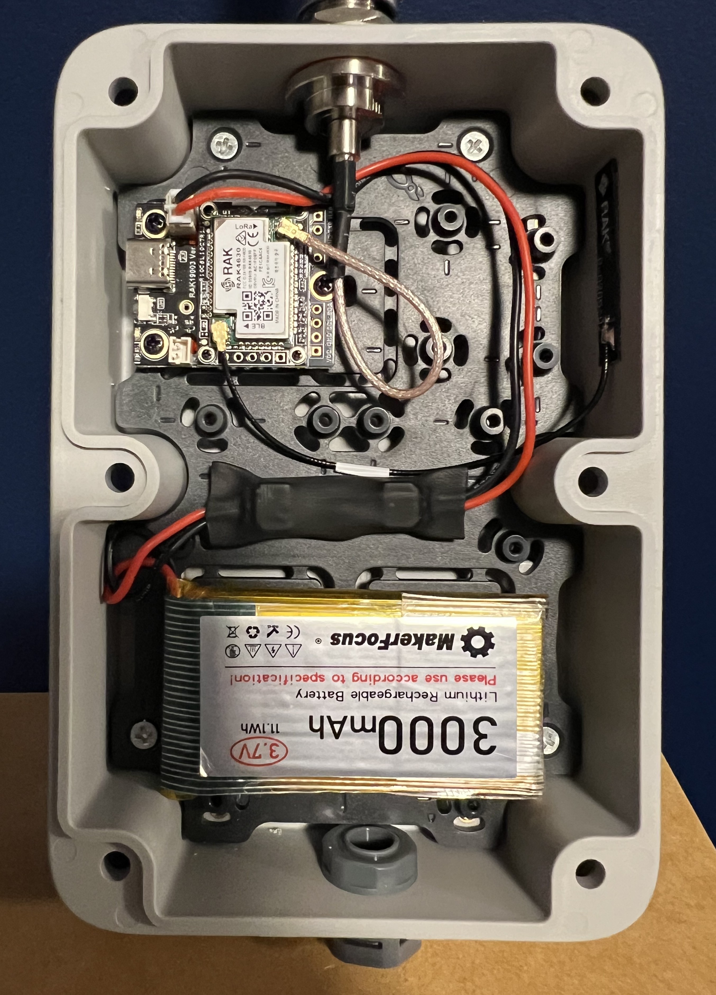
- Mount the RAK backplate with the supplied hardware.
- Mark separate openings for the N-type bulkhead and vent. Drill slowly with suitable protection, deburr the holes, and test-fit after each step.
- Install the bulkhead and vent using the reviewed seals and orientation.
- With all power disconnected, attach the radio-side pigtail to the correct LoRa connector.
- Install the Bluetooth antenna described by the exact board documentation.
- Attach the external LoRa antenna before any power or transmit test.
Checkpoint: the RF path is mechanically secure, unforced, correctly mated, and attached before power.
Stage 3 — Flash and dry-fit
- Keep the unit open and accessible.
- Follow the safe repeater flashing guide for the exact board.
- Mount the radio on the backplate and confirm that cables are not pinched or sharply bent.
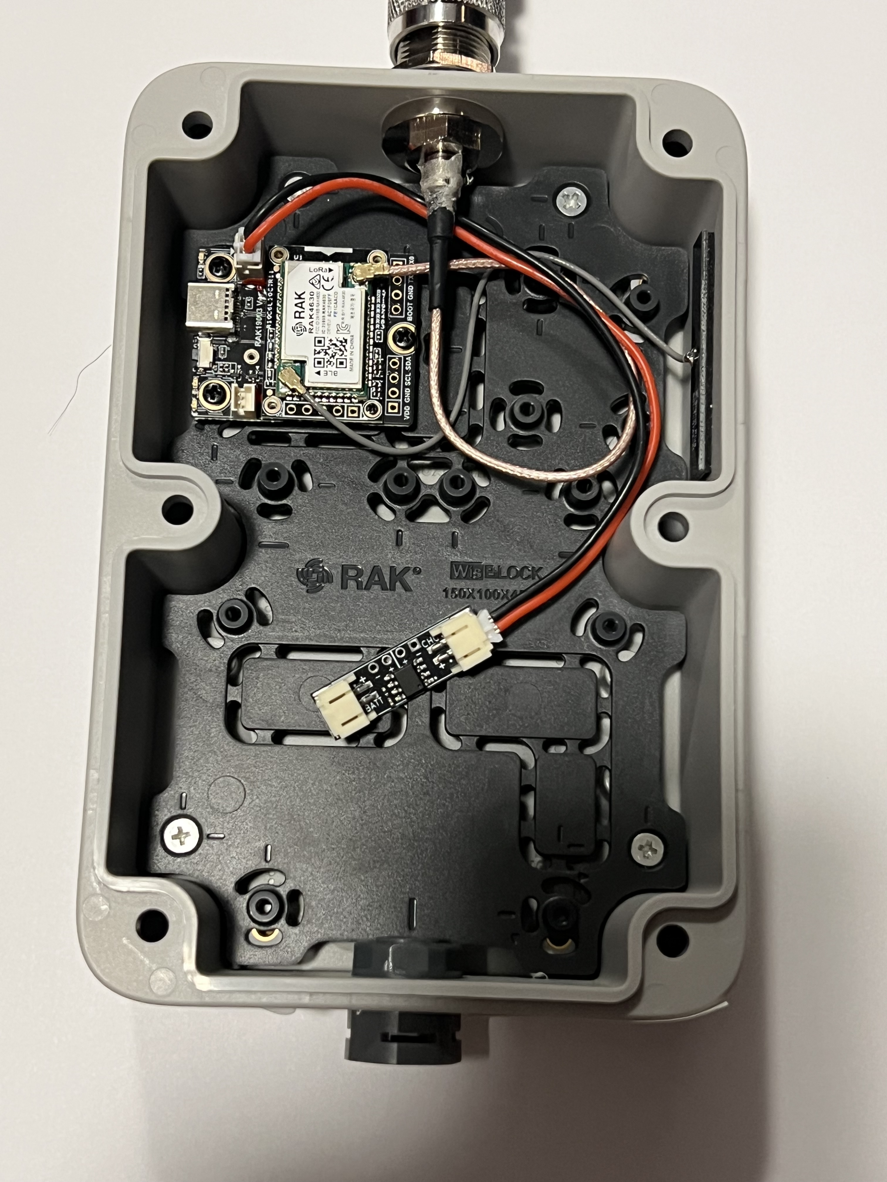
Stage 4 — Verify and connect the power path
- With power disconnected, identify the battery, charger, and any protection-board terminals from their current manufacturer documentation.
- Verify both JST cable polarities with a multimeter; do not rely on wire colour alone.
- Connect the charger side and battery side only according to the reviewed diagram for the exact protection device.
- Insulate and mechanically secure the protection board and battery without crushing, heating, puncturing, or trapping them against sharp edges.
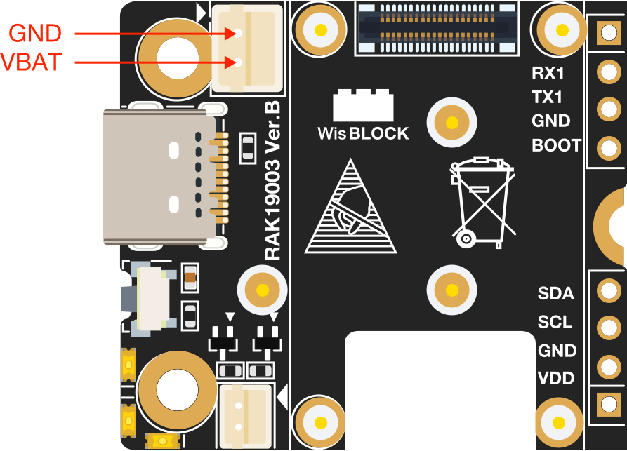
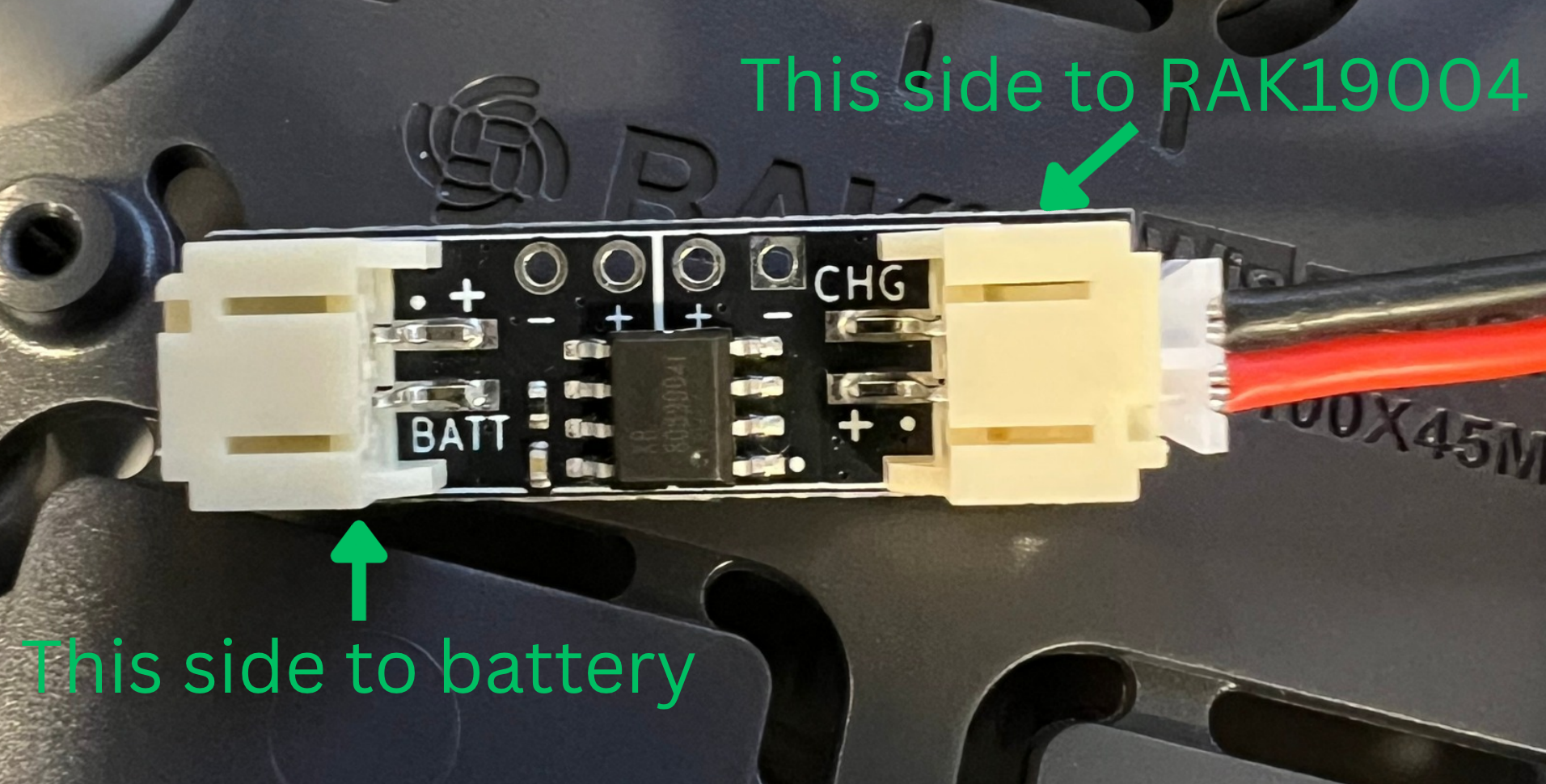
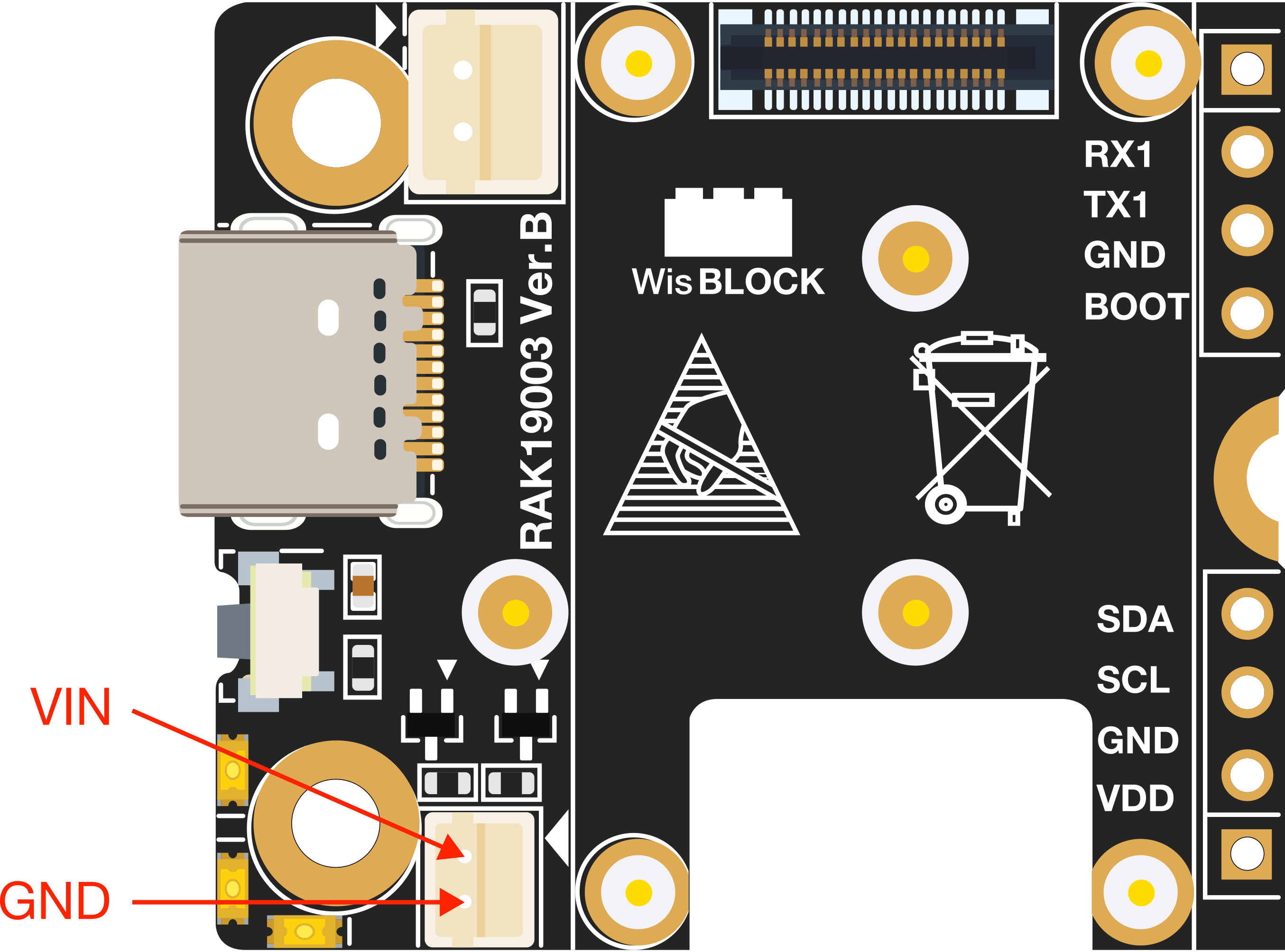
Stage 5 — Seal only after bench verification
- Fit the enclosure gasket without twisting or pinching it.
- Connect the enclosure solar lead only after its polarity and limits are confirmed.
- Close the enclosure evenly with the specified hardware and torque/process from its documentation.
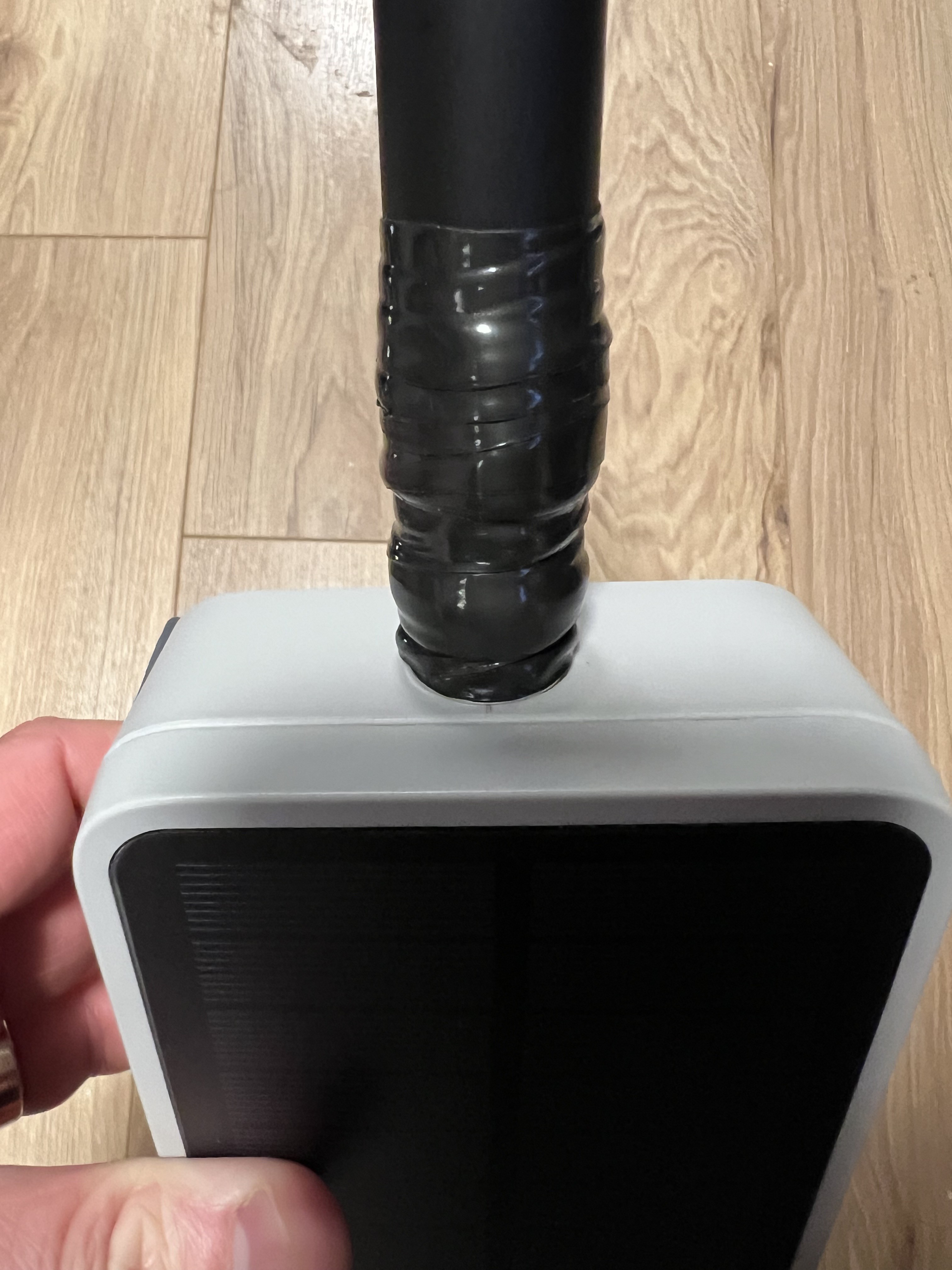
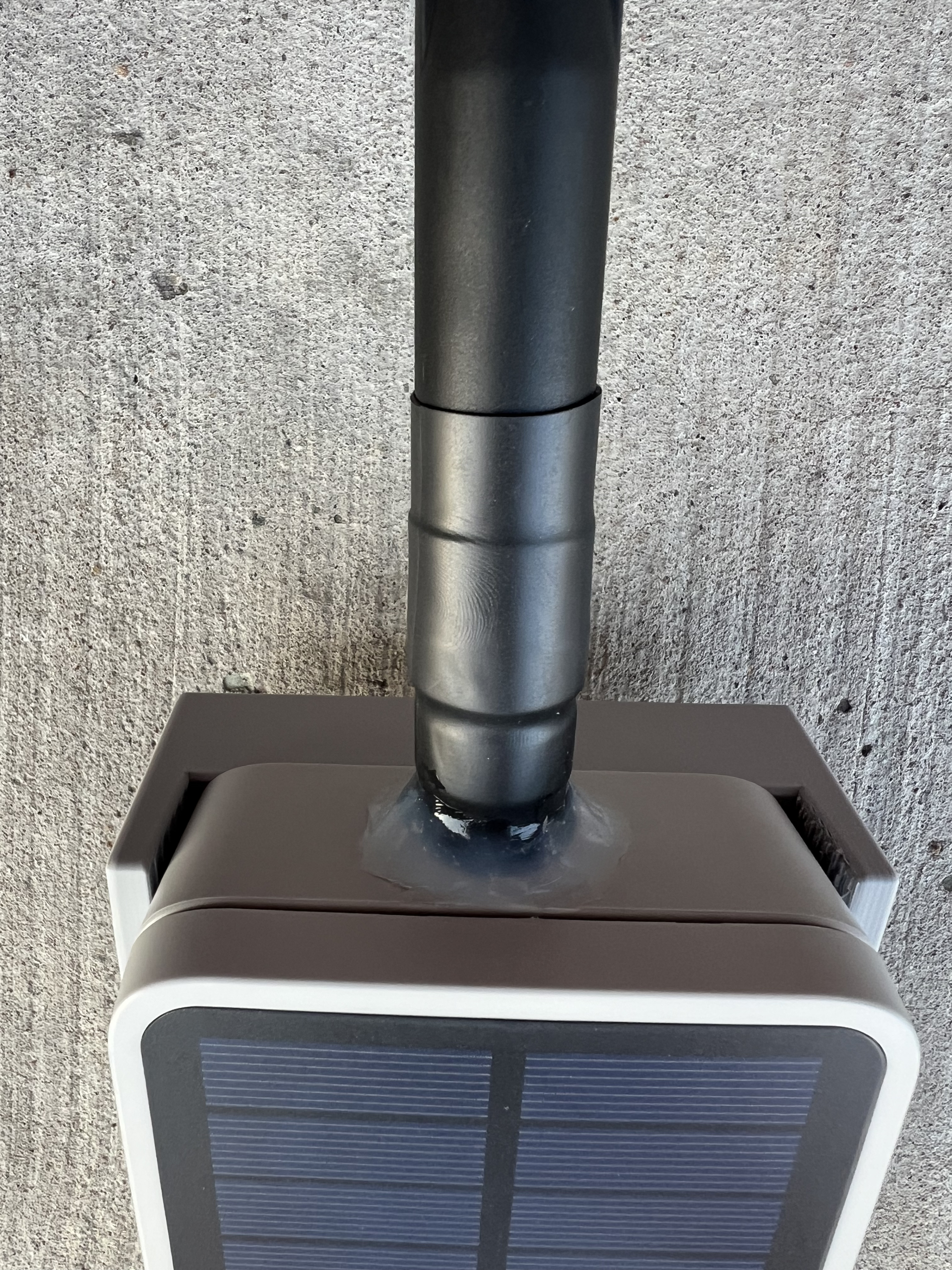
- Apply the reviewed outdoor weather-sealing method to the exposed antenna connection without blocking drainage or venting.
Check the readings
No numeric electrical acceptance range has been peer-reviewed for this page. Use the current manufacturer limits for the exact battery, charger, protection device, radio board, and panel.
| Check | Acceptable result | Stop condition |
|---|---|---|
| Power disconnected continuity | No unintended short across the documented supply path | Unexpected continuity, unstable reading, or uncertain meter setup |
| Polarity | Every connector matches its documented polarity before mating | Wire colour and measured/documented polarity disagree |
| Battery and solar input | Measured values remain within every component's published limits | Any value is outside a limit or the limit is unknown |
| First power | No heat, odour, swelling, smoke, noise, or unstable restart | Any abnormal physical or electrical behaviour |
| Radio current/operation | Behaviour is consistent with the reviewed board and role documentation | Current draw or behaviour cannot be explained from evidence |
Test it on the bench
- Photograph and record the exact parts, revisions, wiring, polarity checks, and measured values.
- Power from a supervised, current-limited bench source where appropriate for the reviewed hardware.
- Confirm the repeater boots, reconnects, and retains firmware, identity, radio, region, advert, and access settings after reboot.
- Confirm a nearby companion receives an advert and the planned local routing test succeeds.
- Exercise the intended solar/charge path under supervised conditions supported by the component documentation.
- Inspect seals and cable strain before and after a controlled water-resistance check appropriate to the enclosure documentation.
- Keep USB recovery practical and record the recovery procedure.
Do not mount the build until all checks pass and a hardware reviewer approves the site record.
Recovery and undo
If a check fails, disconnect solar, USB, and battery power using the documented safe sequence. Move the unit to a non-combustible supervised work area, inspect for heat or battery damage, and do not reconnect a questionable lithium battery. Restore the last known-good board configuration by USB only after the electrical fault is resolved.
Mechanical holes and adhesive/sealant work may not be reversible; replace damaged or uncertain enclosure and power parts rather than improvising a repair.
Maintenance
No Canada-wide interval is approved. Before deployment, record a site-specific inspection schedule covering mount movement, water entry, seals, corrosion, cable strain, battery condition, charging behaviour, measured values, firmware/configuration, radio verification, and physical recovery.
Source
Based on community build notes contributed by MrAlders0n in 2026. The parts and instructions still require hardware review.
After the bench test, complete the mounting plan and set the repeater's region with the configurator.