Experimental 1 W Solar Repeater
This unverified design combines an Ikoka Stick 0.4.0, a solar power manager, a filtered RF path, and a fabricated enclosure.
Do not build or deploy this design without electrical, RF, and site review. Its firmware target, electrical design, optional telemetry, measurements, and climate limits have not been reproduced.
- Radio
- GOME Ikoka Stick 0.4.0
- Power
- Waveshare Solar Power Manager
- Firmware
- Not pinned or reproduced
- Maintenance
- Set during the site review
Is this build appropriate?
This is a specialized backbone or long-range experiment, not a default upgrade. Coordinate with nearby communities and show that the site needs it before changing coverage or traffic patterns.
Use the 300 mW draft build or a reviewed pre-built path unless a network operator and hardware/RF reviewer agree that this experiment addresses a measured need.
Before you start
This combines high-power RF, lithium batteries, charging, soldering, cutting, and an outdoor elevated installation
Verify every component and limit from current manufacturer documentation. Keep an antenna and reviewed RF path attached before any transmit test. Do not energize a battery or charger path when polarity, protection, wiring, temperature, or expected readings are unknown.
- The local network need and cross-region effects are documented.
- The exact Ikoka hardware and repeater firmware target are confirmed and recoverable by USB.
- A hardware/electrical reviewer approves the battery, charger, panel, wiring, protection, optional telemetry, and enclosure thermal plan.
- An RF reviewer approves the radio, filter, feed line, antenna, connectors, and site.
- A structural/site review covers the finished mass, panel area, mount, wind, ice, snow, cable route, and access.
- The build will remain supervised on the bench until its test record is approved.
What this build changes
The procedure cuts and drills an enclosure, bonds a solar panel with epoxy and sealant, modifies the mounting system, connects a high-power RF path and filter, assembles a lithium power system, and may remove display pins for optional telemetry. Several changes are difficult or impossible to undo without replacing parts.
Bill of materials to verify
| # | Part | Qty | Detail to verify | Source |
|---|---|---|---|---|
| 1 | GOME Ikoka Stick 0.4.0 | 1 | Hardware revision, Canadian band, RF output, firmware target, recovery | Project page |
| 2 | Waveshare Solar Power Manager | 1 | Exact model, panel, battery and output limits, startup behaviour, temperature | Waveshare |
| 3 | IP65 junction box, 220×170×110 mm | 1 | Material, ingress rating after modification, temperature, vent | AliExpress |
| 4 | 10 W / 18 V panel, 250×340 mm | 1 | Electrical limits, dimensions, mass, weather and load suitability | Amazon |
| 5 | 3P1S or 4P1S 18650 pack | 1 | Chemistry, matched cells, protection, construction, charger, temperature | MP&W Supply |
| 6 | Battery protection board | 1 | Thresholds, current, temperature, wiring, compatibility | Space Hedgehog |
| 7 | 890–960 MHz four-cavity band-pass filter, 50 W | 1 | Response at 902–928 MHz, insertion loss, connectors, weather, temperature | Alibaba |
| 8 | 10–15 cm SMA right-angle to N-type female bulkhead cable | 1 | Connector gender and polarity, loss, bend, seal | AliExpress |
| 9 | 7.5 cm SMA male right-angle cable | 1 | Connector match, loss, bend, power handling | AliExpress |
| 10 | 0.5 ft USB-A to USB-C right-angle cable | 1 | Data and power needs, current, fit, strain | Amazon |
| 11–12 | M3×35 spacers and M3×5 screws | as needed | Material, strength, fit, corrosion | Local source |
| 13 | Gorilla Epoxy, 25 ml | 1 | Material compatibility, cure, outdoor and temperature limits | Home Depot |
| 14 | Waterproof vent plug | 1 | Thread, airflow, ingress performance after install | AliExpress |
| 15 | Clear outdoor silicone sealant | 1 | Material compatibility, cure, UV and temperature limits | Local hardware source |
| 16 | Adafruit INA3221, optional | 1 | Electrical interface, address, firmware support, isolation, calibration | DigiKey |
These parts are unverified leads. Check current specifications, availability, shipping, and total cost before buying.
Tools and downloads
Plan for soldering and wire tools, a multimeter, suitable drills and cutting tools, clamps, eye protection, and a safe work area.
Printable files to verify:
Confirm dimensions, material, temperature performance, fasteners, battery restraint, and print quality before use.
Assembly stages
Stage 1 — Review and dry-fit
Confirm all revisions, dimensions, electrical limits, connector paths, filter orientation, clearances, printed parts, cable bends, vent location, panel location, and service access before cutting or bonding.
Checkpoint: the reviewed schematic, RF path, and mechanical layout agree with the exact parts in hand.
Stage 2 — Prepare the enclosure and panel
- Measure the panel junction box and mark the enclosure cutout from the actual parts.
- Use an appropriate pilot opening and cutting tool with the enclosure empty and safely supported.
- Deburr and clean the cutout, then dry-fit the panel and cable route.
- Bond and clamp only with a reviewed material-compatible process. Let it cure for the full manufacturer time.
- Apply the reviewed weather seal without blocking drainage or venting.
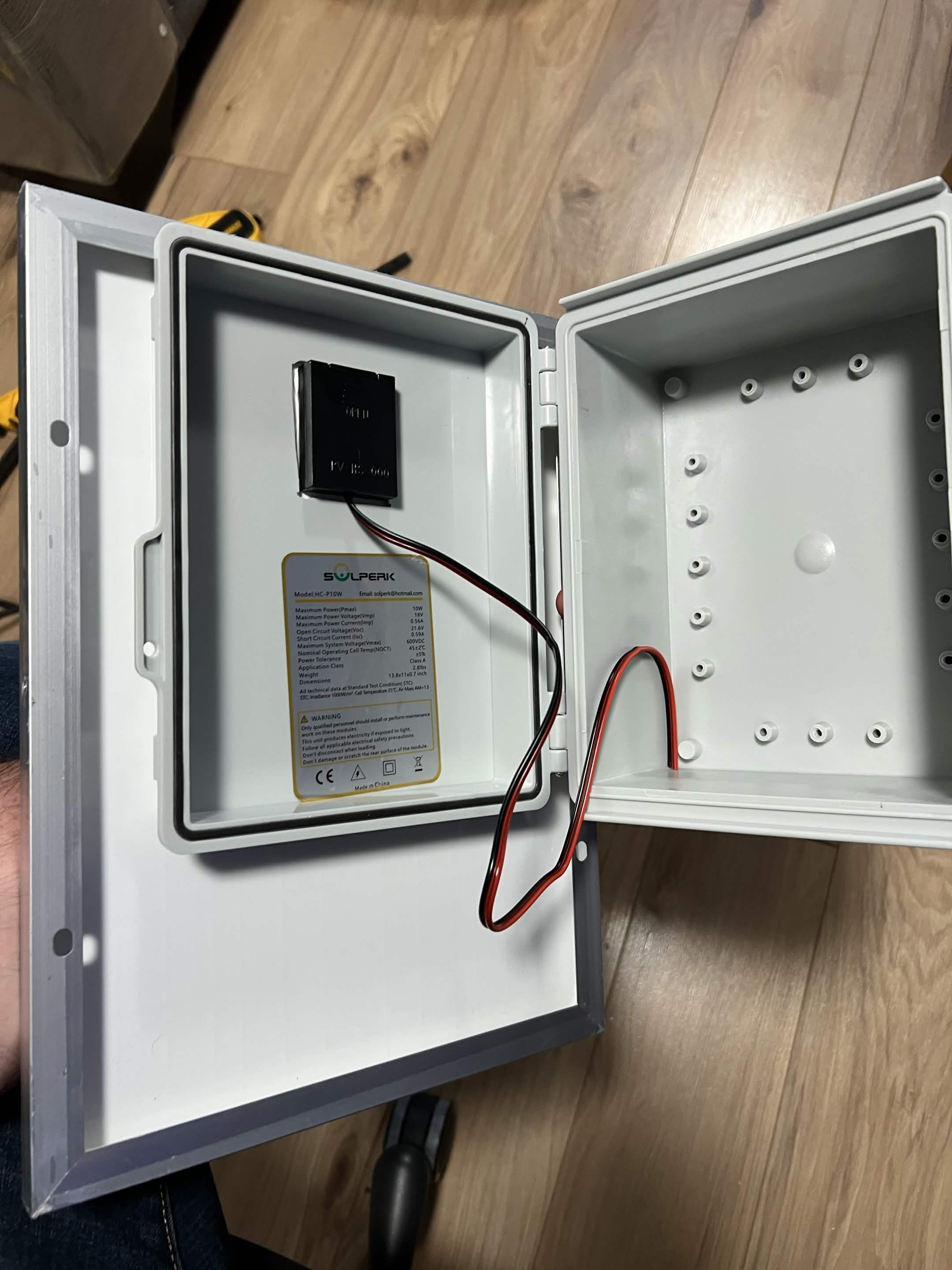
Stage 3 — Install the mounting plate, filter, bulkhead, and vent
- Fit the reviewed spacers and mounting plate without stressing the enclosure.
- Mount the filter with identified input and output ports and adequate cable bend radius.
- Drill and deburr the bulkhead and vent holes by test-fitting the actual hardware.
- Install seals, bulkhead, and vent according to their documentation.
- Leave RF connections unpowered and accessible for inspection.
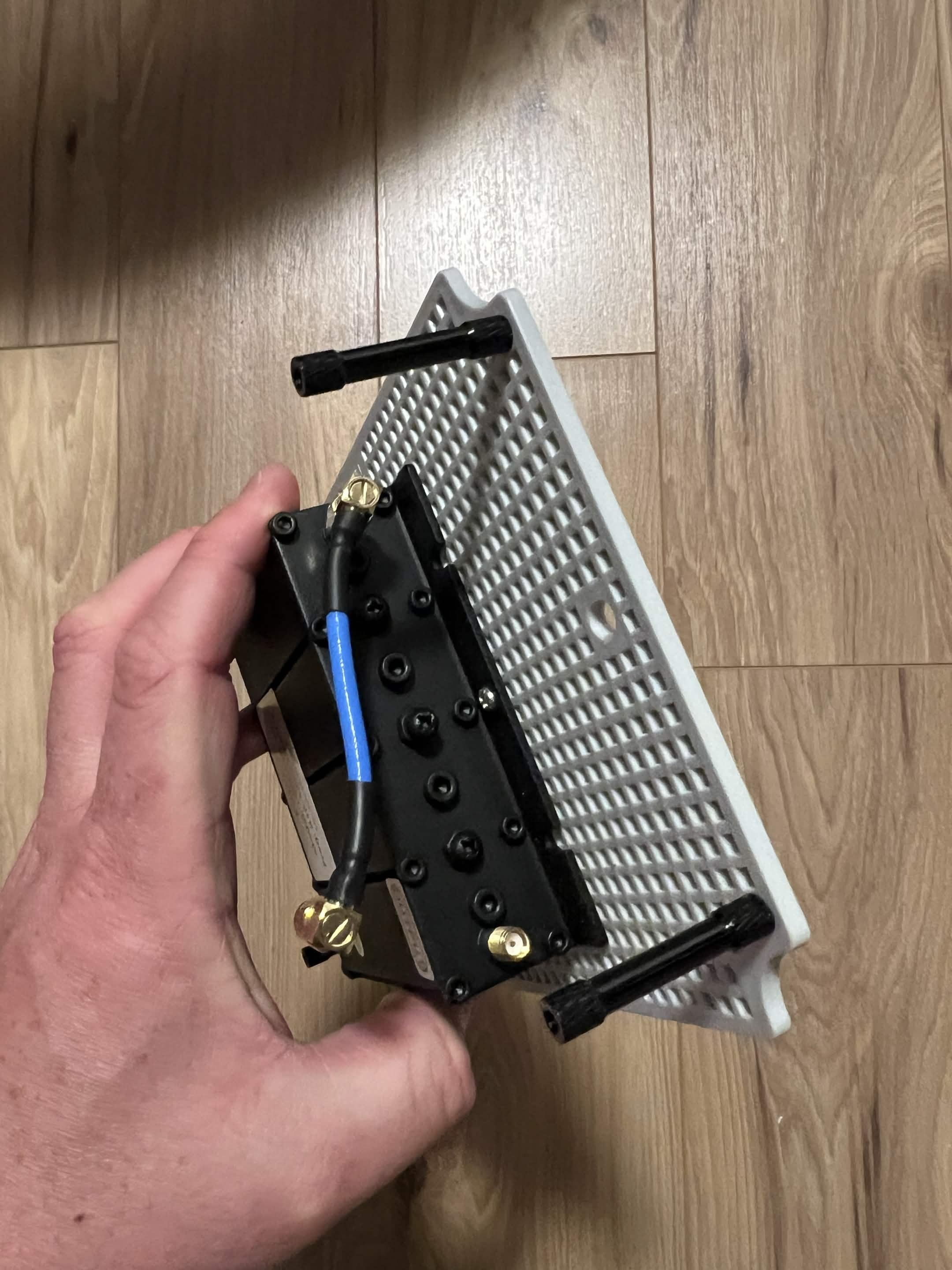
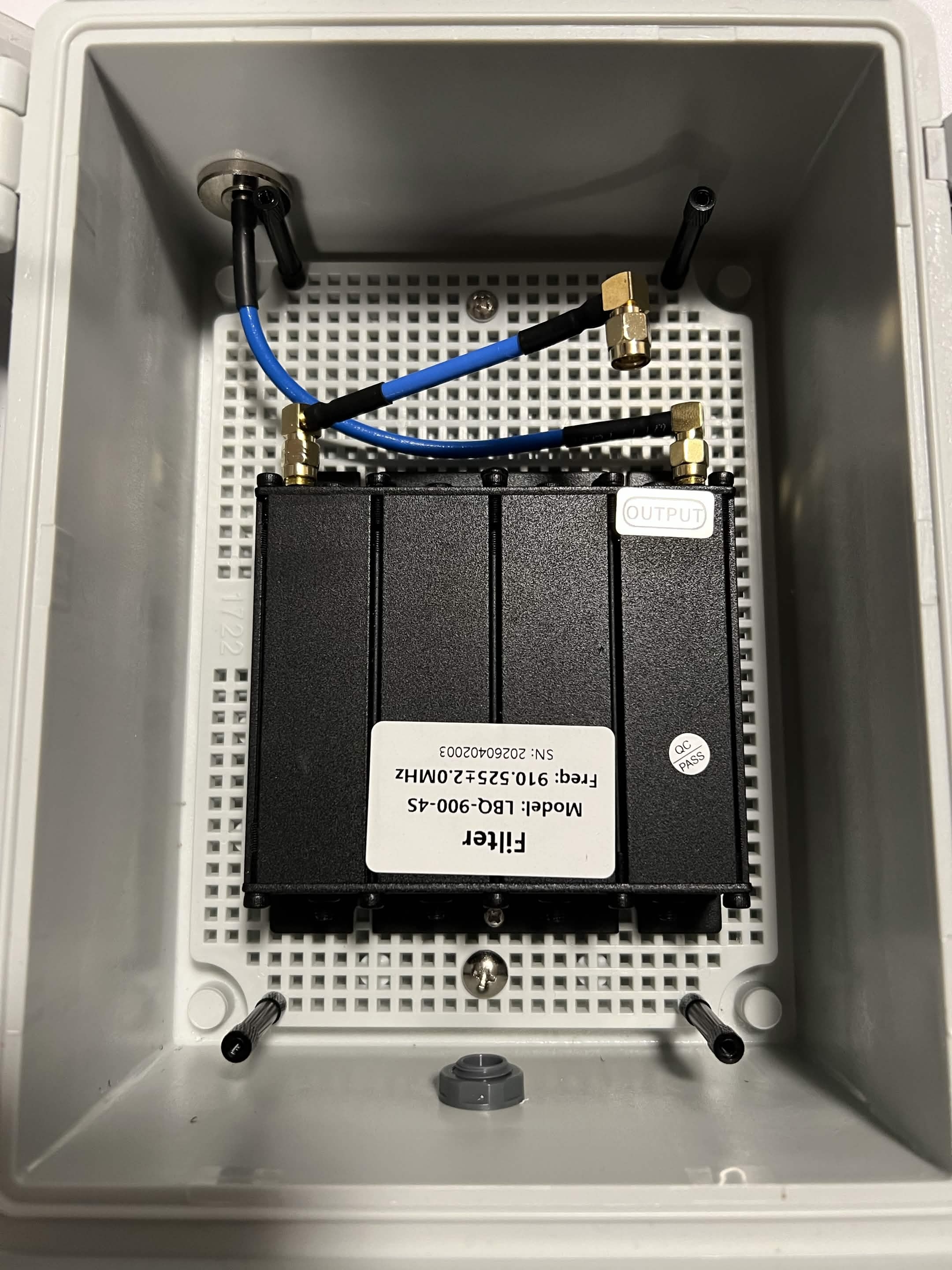
Stage 4 — Review the power-manager startup modification
Do not bridge the power manager's boot-button pads. That modification has not been reproduced or reviewed.
Before considering any change, require the exact schematic, failure modes, warranty impact, soldering method, startup test, and rollback to be approved by a hardware reviewer.
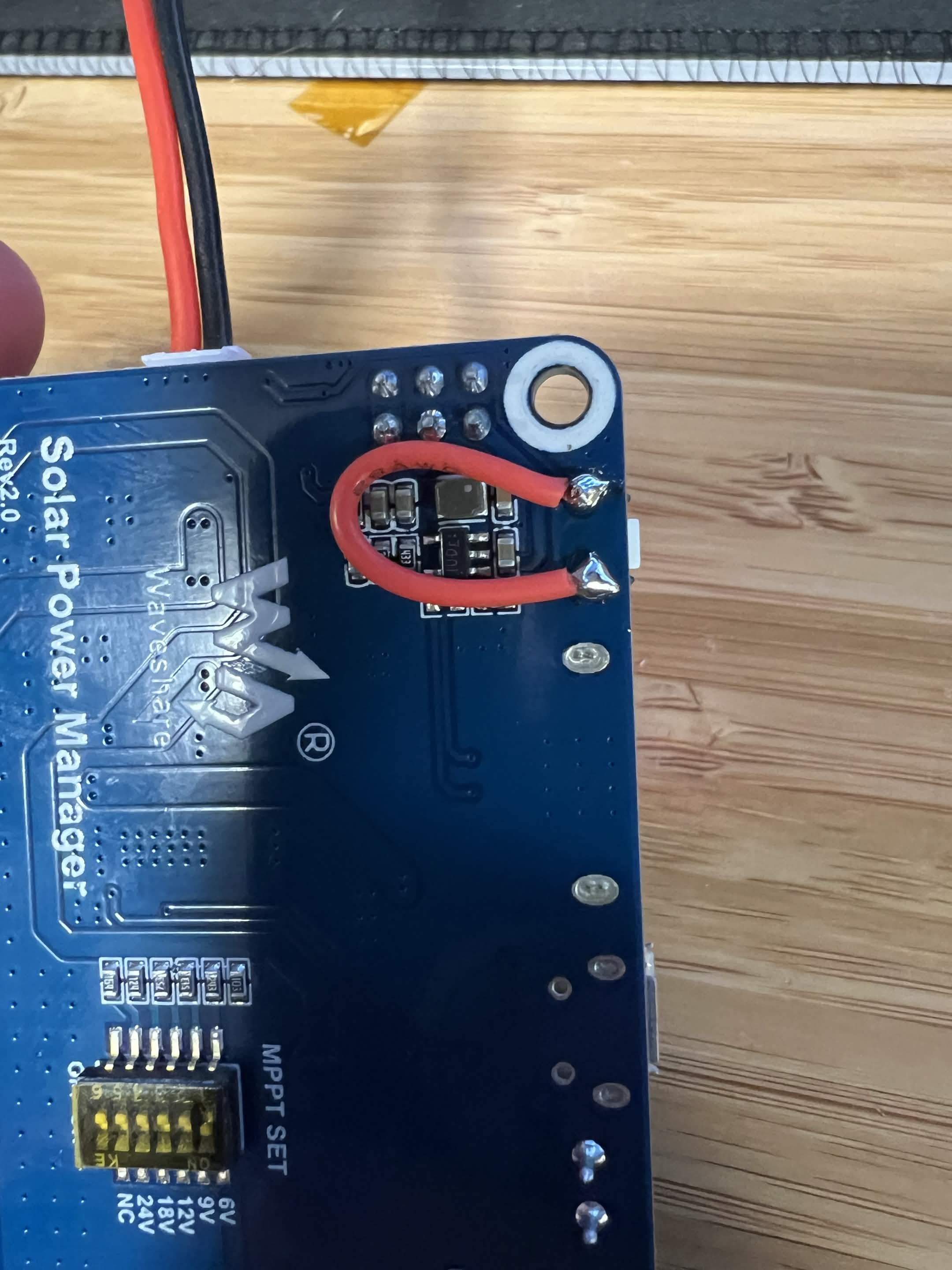
Stage 5 — Mount the radio and decide on optional telemetry
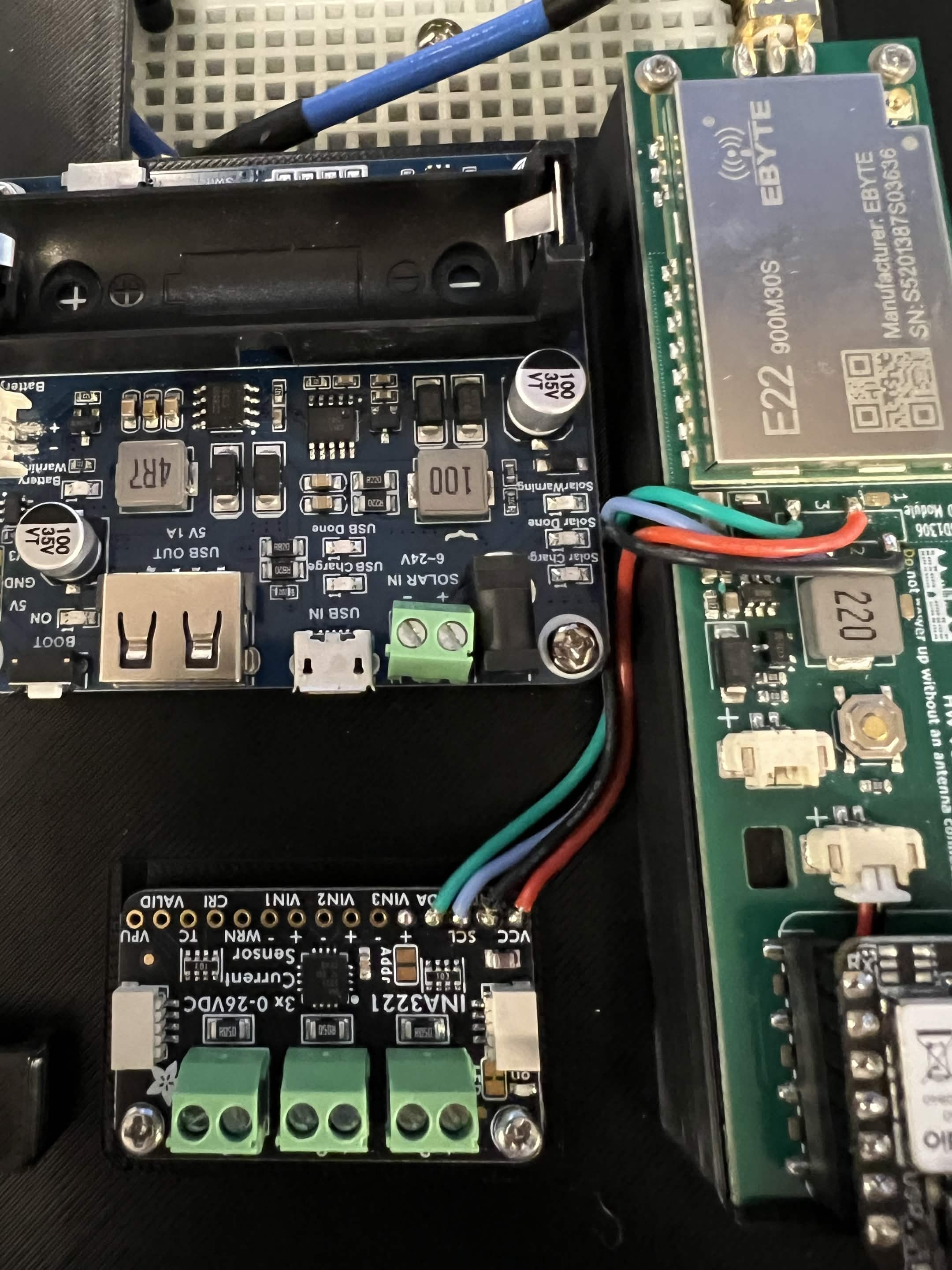
Dry-fit the Ikoka Stick and power manager. The optional INA3221 branch removes the display header and solders to I2C pads, so it must remain separate from the base build.
The telemetry pinout, measurement path, calibration, current range, I2C address, and firmware support are not verified.
Default: omit optional telemetry. Do not remove display pins or add firmware flags until the exact hardware and current MeshCore target are reproduced.
Stage 6 — Assemble the battery and charging path
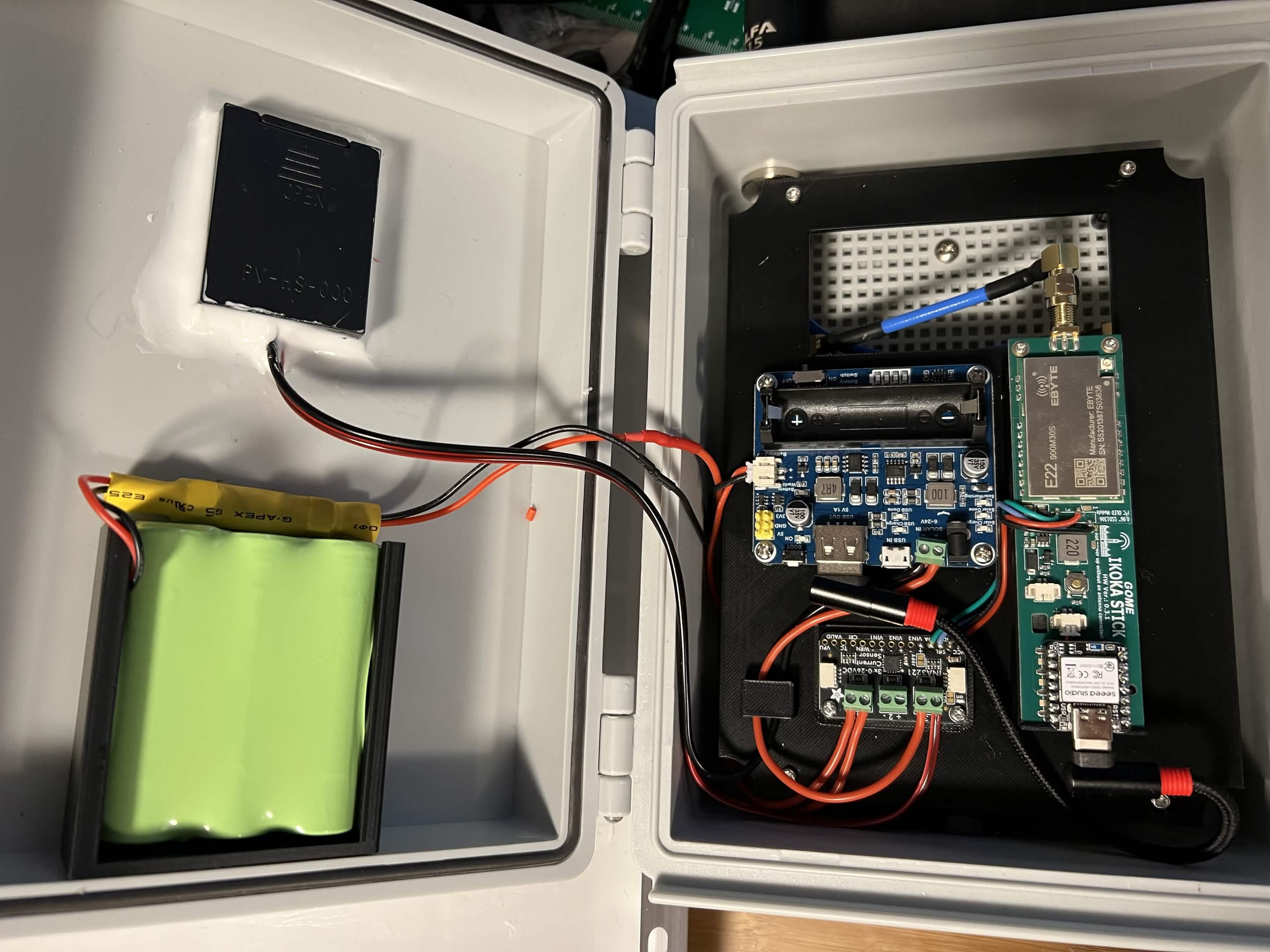
- Keep solar, battery, USB, and radio disconnected.
- Confirm the battery pack construction, cell matching, protection, restraint, insulation, and temperature limits.
- Confirm every power-manager and protection-board terminal from current manufacturer documentation.
- Measure and record polarity; do not rely on wire colour.
- Connect one reviewed branch at a time and inspect before proceeding.
Checkpoint: no unknown terminal, limit, expected value, exposed conductor, or unsupported battery condition remains.
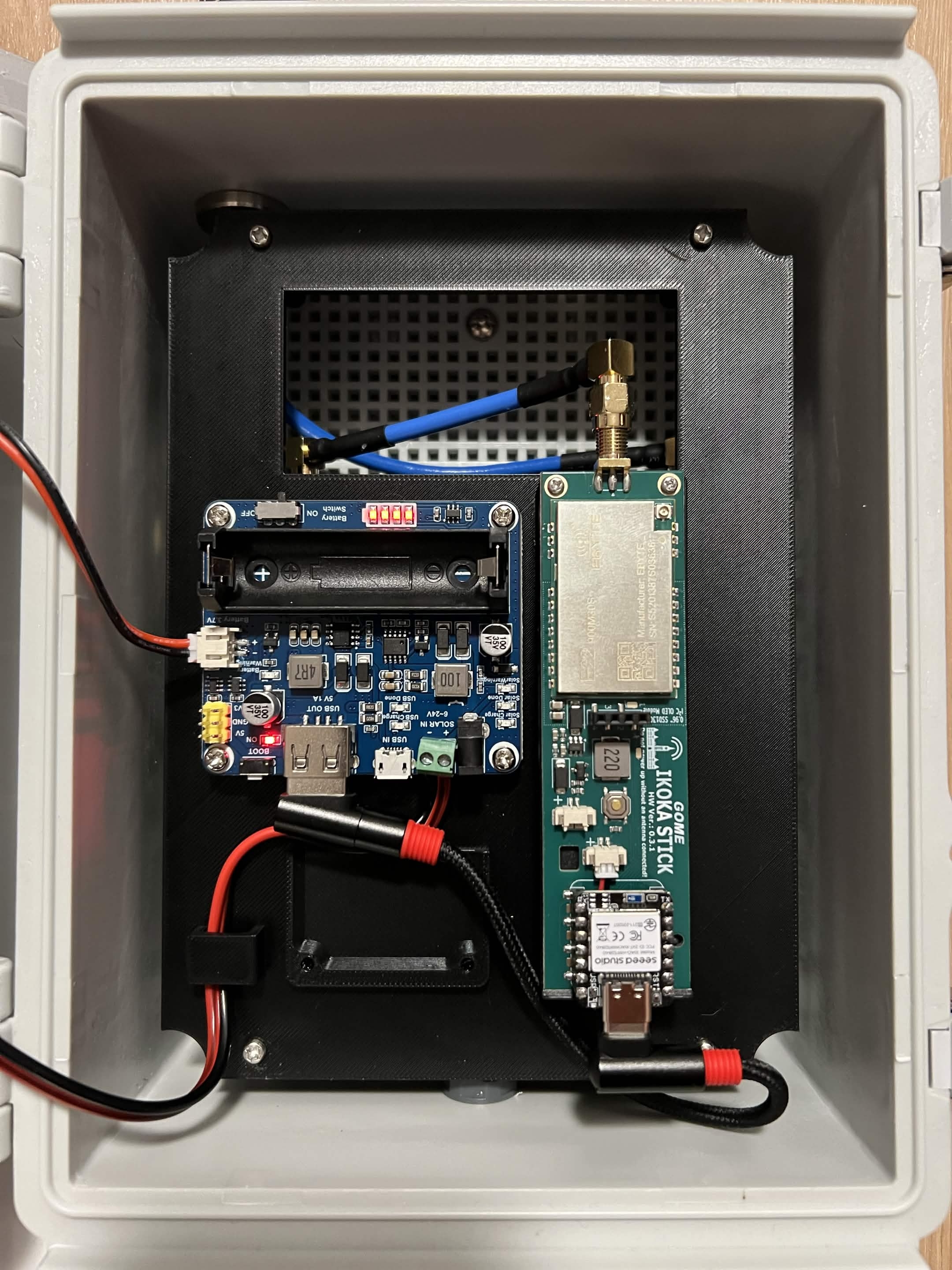
Stage 7 — Complete the RF and USB paths
- Verify filter input/output direction and every SMA/N-type connector.
- Attach the complete reviewed antenna path before the radio can transmit.
- Route the USB power cable without sharp bends, abrasion, or strain.
- Keep the enclosure open for supervised first power and checks.

Check the readings
No numeric acceptance range has been peer-reviewed for this page. Do not substitute guessed voltages or currents.
| Check | Acceptable result | Stop condition |
|---|---|---|
| Disconnected continuity | No unintended short on the documented supply or RF paths | Unexpected continuity or uncertain meter setup |
| Connector polarity | Measurements match the reviewed schematic and manufacturer pinout | Any disagreement or unknown pin |
| Solar, battery, and output values | Each measured value is within every connected component's current documentation | Missing limit or out-of-range value |
| First power | Stable expected startup with no heat, odour, swelling, smoke, noise, or cycling | Any abnormal physical or electrical behaviour |
| RF path | Correct band, filter direction, connections, and attached antenna before transmit | Missing antenna, loose/forced connector, unknown filter response |
| Optional telemetry | Independently reproduced measurement and firmware behaviour | Unverified wiring, address, calibration, or build target |
Test it on the bench
- Record exact parts, revisions, source documents, schematic, photographs, polarity, and measured values.
- Use supervised and current-limited first-power methods appropriate to the reviewed hardware.
- Confirm the unit starts after each intended power source is applied and after a controlled power interruption.
- Confirm the repeater's identity, firmware, radio, region, path, advert, and access settings survive reboot.
- Confirm a nearby companion receives an advert and the planned local routing test succeeds.
- Measure the RF/power behaviour using the reviewer's approved method; do not infer output from a firmware setting alone.
- Run a supervised charge/load test that covers the reviewed conditions without exceeding component limits.
- Inspect cable strain and seals, then complete an enclosure-appropriate water-resistance test.
- Prove USB recovery and document the removal/access plan.
Do not deploy until a hardware/electrical reviewer, RF reviewer, and site owner approve the completed test record.
Recovery and undo
If a check fails, stop transmitting and disconnect solar, USB, and battery power using the reviewed safe sequence. Move the equipment to a suitable supervised work area. Do not reconnect a warm, swollen, damaged, leaking, or otherwise questionable lithium battery. Restore firmware by USB only after the electrical/RF fault is understood.
Cutouts, epoxy, removed pins, and solder bridges may be irreversible. Replace uncertain components rather than improvising a repair. The safe rollback from the optional telemetry branch is to omit it before modification, not to assume removed hardware can be restored.
Maintenance
No interval is approved. The site record must define inspections for mounting, panel/bond, water entry, vent, seals, corrosion, cables/connectors, filter, battery condition, charge behaviour, measured values, firmware/configuration, radio verification, and physical recovery. Reinspect after any severe event or unexplained behaviour defined by the site reviewer.
Source
Based on experimental community notes contributed by MrAlders0n in 2026. No hardware or firmware claim on this page is verified.
Prefer a reviewed option from the repeater selection guide. If this experiment is approved and commissioned, complete the mounting plan and repeater configuration.